
Every production line faces silicone defects. What matters is how quickly we find the root cause and correct it.
Understanding the root causes of flow marks, flash, bubbles, scorching, and tears helps engineers rapidly identify and fix silicone molding issues.
When I started working on silicone molding, I used to think defects were random. But after reviewing hundreds of molds and production runs, I learned that every defect follows a pattern — if you can trace it, you can fix it.
Defect Classification and Judgment Criteria?
Before solving defects, we must first identify and classify them correctly. Misjudging a defect leads to wasted time and incorrect countermeasures.
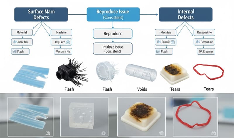
Silicone defects can be classified by visual appearance, occurrence pattern, and process stage to determine their root cause.
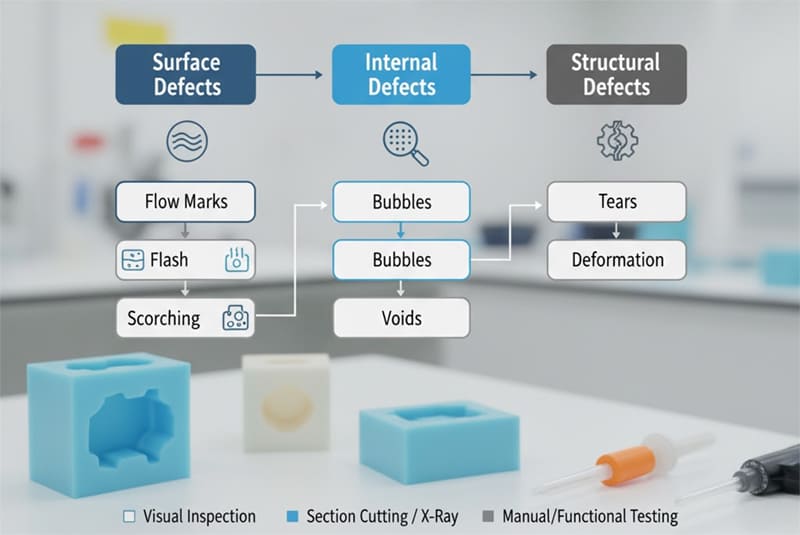
We usually classify defects into surface, internal, and structural categories. Each has specific visual indicators and testing methods.
Silicone Defect Classification Table
| Category | Typical Defects | Key Indicators | Detection Method |
|---|---|---|---|
| Surface | Flow marks, flash, scorching | Visible irregularities | Visual inspection |
| Internal | Bubbles, voids | Cross-section analysis | Section cutting, X-ray |
| Structural | Tears, deformation | Functional failure | Manual testing, visual |
Each defect has a tolerance range defined in the appearance standard. For example, a 0.2 mm flow mark on a non-visible surface may be acceptable, but the same on a sealing surface is a rejection.
Typical Defect Mechanisms?
Every defect has a mechanical or chemical root cause. Understanding how they form allows faster troubleshooting during production.
Flow marks, flash, bubbles, scorching, and tears originate from specific process or mold-related mechanisms.
1. Flow Marks
Flow marks appear as wavy or streaky lines on the surface.
| Root Cause | Mechanism | Remedy |
|---|---|---|
| Low mold temperature | Silicone cures unevenly | Increase temperature 10–15°C |
| Unbalanced injection | Flow front overlaps | Adjust gate size or position |
| Contaminated mold | Residue interrupts flow | Clean cavity and apply mold release evenly |
2. Flash
Flash occurs when silicone leaks through parting lines or vents.
| Root Cause | Mechanism | Remedy |
|---|---|---|
| Insufficient clamping force | Gap between mold halves | Increase clamping pressure |
| Worn parting line | Seal surface wear | Polish or regrind mold |
| Excessive vent depth | Silicone seepage | Reduce vent depth to 0.005–0.01 mm |
3. Bubbles
Bubbles form due to trapped air or volatile gases.
| Root Cause | Mechanism | Remedy |
|---|---|---|
| Poor venting | Air trapped during filling | Add or enlarge vents |
| Excess moisture | Vaporizes under heat | Dry silicone before molding |
| Vacuum malfunction | Air not evacuated | Check vacuum seal and system timing |
4. Scorching
Scorching creates dark, burnt marks or surface discoloration.
| Root Cause | Mechanism | Remedy |
|---|---|---|
| Excessive dwell time | Silicone overheats | Reduce cure time or dwell duration |
| Localized hot spots | Temperature imbalance | Inspect heater zones |
| Contaminated additives | Catalyst reaction | Use fresh and verified material |
5. Tears
Tears occur during demolding or under stress.
| Root Cause | Mechanism | Remedy |
|---|---|---|
| Low tear strength silicone | Inadequate formulation | Choose higher tear-grade LSR |
| Sharp undercuts | Mechanical stress | Increase draft or use flexible cores |
| Premature demolding | Not fully cured | Extend curing time 10–20% |
Mapping of Process Parameters and Mold Factors?
Defects do not occur randomly — they are connected to process parameters and mold conditions. Mapping helps visualize these relationships clearly.
Linking process parameters with defect types reveals hidden dependencies and allows targeted optimization.
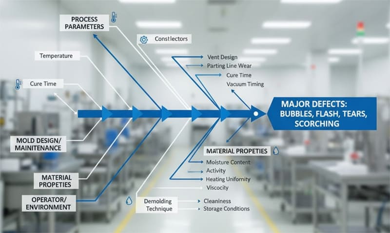
When I investigated recurring bubbles in a medical valve mold, I created a fishbone diagram linking temperature, venting, and material flow. The root cause turned out to be uneven vacuum timing — not the silicone itself.
Parameter–Defect Mapping Example
| Parameter | Too Low | Too High | Related Defect |
|---|---|---|---|
| Mold temperature | Flow marks | Scorching | Surface defects |
| Injection pressure | Short shot | Flash | Dimensional instability |
| Curing time | Incomplete cure | Scorching | Structural and color issues |
| Vacuum time | Bubbles | Flash | Air entrapment or overflow |
| Mold vent depth | Bubbles | Flash | Air or silicone leakage |
Why Is Flash Control Recurring?
Flash tends to recur when sealing surfaces degrade over time or when operators adjust injection pressure beyond the validated window. Regular maintenance and machine parameter locks prevent this recurrence.
Rapid Localization and Experimental Methods?
Time is critical during production. A structured troubleshooting approach helps engineers identify the defect source faster.
Systematic localization using sampling, section analysis, and controlled trials narrows down the root cause efficiently.
During a new mold trial, we found random bubbles only in cavity #3. By isolating that cavity and running a test under different vacuum timings, we confirmed a blocked vent near the gate. The key is to verify one variable at a time.
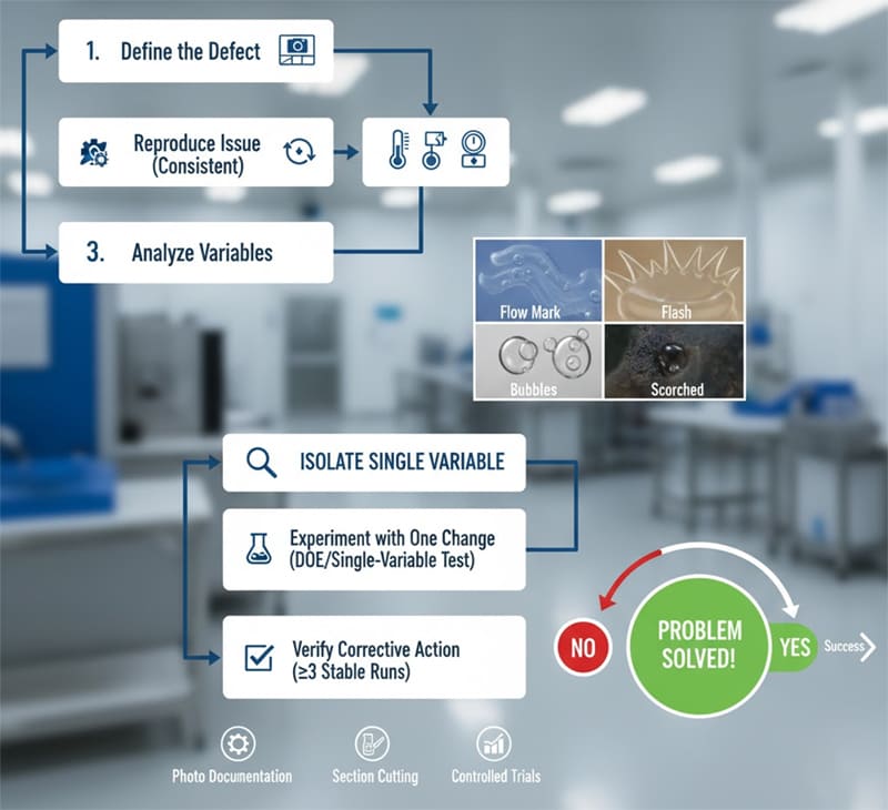
Step-by-Step Troubleshooting Method
- Define the defect with photo documentation and location mapping.
- Reproduce the issue consistently under controlled settings.
- Analyze variables such as temperature, vacuum, and pressure.
- Experiment with one change at a time (DOE or single-variable test).
- Verify the corrective action with at least three stable runs.
What Is the Relationship Between Scorching and Dwell Time?
Scorching often increases exponentially with longer dwell time. When silicone stays in the heated cavity too long, peroxide or platinum catalysts degrade, causing discoloration and odor. Shortening dwell by even 10% can eliminate scorching completely.
Preventive Control Plan?
The best solution is prevention. Once root causes are known, standardized control plans can stop defects from recurring.
A preventive control plan links each defect type to its process, mold, and maintenance control points.
In my plant, we built a “defect-prevention matrix” after analyzing hundreds of production records. By tracking mold wear and monitoring curing temperature daily, we reduced flash and bubbles by 60% within two months.
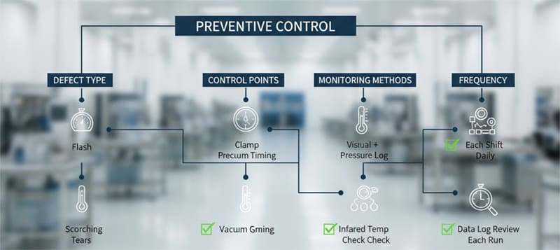
Example Preventive Control Plan
| Defect Type | Control Point | Monitoring Method | Frequency |
|---|---|---|---|
| Flash | Clamp pressure, vent depth | Visual + pressure log | Each shift |
| Bubbles | Vacuum timing, vent cleaning | Vacuum gauge check | Daily |
| Flow marks | Mold temp uniformity | Infrared temp check | Weekly |
| Scorching | Cycle time, mold heater | Data log review | Each run |
| Tears | Draft angle, demold temperature | Mold inspection | Weekly |
A good preventive plan includes both process validation and operator training. Consistency is achieved only when everyone follows the same standard.
Conclusion
Every silicone defect tells a story. When we understand its cause and link it to process variables, troubleshooting becomes systematic and predictable — not guesswork.
Want to solve your silicone defect faster?
Submit your defect photos and parameter records to our engineering team, and we’ll send back a custom troubleshooting checklist to help you restore stable production at RuiYang Silicone.