Undercuts often cause trouble on the production floor. If a part has an unplanned undercut, it may stick during ejection. Flexible materials like LSR or TPE stretch, snap, or leave surface marks if the mold design isn’t aligned with material behavior. Small mistakes can cascade. One jammed part can halt a machine for minutes, sometimes hours if the mold needs inspection or adjustment.
Experienced teams quickly learn that planning for undercuts saves time and cost. You don’t just prevent stuck parts. You reduce scrap, minimize tool wear, and avoid extended cycle times. Even minor features, like a snap tab or small groove, can create problems if ignored early in the design stage.
Evaluating Undercut Necessity
Certain features almost always need undercuts:
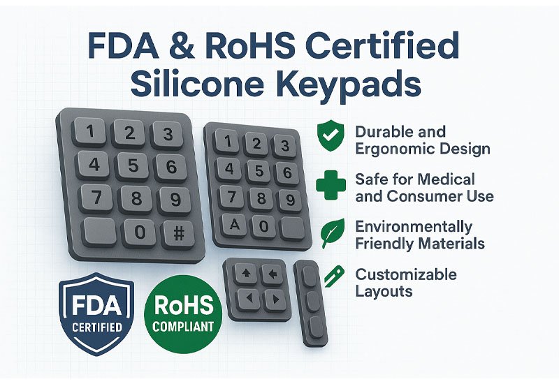
- Snap-fit closures on flip covers or medical housings
- Vertical threads, bosses, or wire slots
- Thick-wall cores to prevent shrinkage and warping
Not every bump or slot demands a side-action core or elastic release. Sometimes, adjusting the wall taper or slightly moving the parting line resolves the issue. On a thin-wall LSR cover, moving a tab by just 1 mm and adding a small draft angle removed the need for two side actions. Cycle time improved and the scrap rate dropped.
When deciding, consider mold complexity, production volume, and ease of maintenance. Sometimes avoiding a side-action is worth redesigning the part slightly. The savings in machining and mold complexity usually outweigh the minor design compromise.
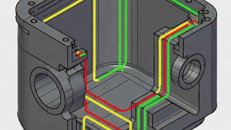
Parting Line Strategy
The parting line determines how the mold separates. It affects part ejection, surface finish, and assembly fit.
Key rules:
- Never place a line on sealing edges or snap-fit surfaces
- Avoid assembly faces where two parts meet
- Zigzag lines help release stress during ejection but increase machining time
- Even 1–2 mm shifts in the line can prevent minor drag marks
Example Table: Parting Line Guidelines
| Feature | Line Placement | Effect | Note |
| Snap-fit tab | Side | Protects surface finish | Draft >2° recommended |
| Thick-wall | Centerline | Reduces sink marks | Slight core taper may be needed |
| Sealing edge | Avoid | Maintains seal | Plan shutoff surface |
Adjusting the parting line early can remove undercut conflicts, reduce mold complexity, and shorten production cycles. On recent projects, moving the line slightly allowed three undercut features to be handled without additional cores.
Bump-Off for Elastic Features
Bump-off uses the material’s elasticity to release minor undercuts. It works best for thin walls, flexible tabs, and small snaps.
Guidelines:
- Lead angle: 30°–45°
- Avoid ribs, sharp corners, or thick zones
- Calculate ejection space to prevent overstretching
On the production line, a thin flexible tab failed repeatedly with small pull marks. Adjusting the bump-off angle to 35° solved the problem. Production ran smoothly, thousands of parts at a time.
Even small adjustments—moving the bump-off point by 0.5 mm or adding 1–2° draft—can remove marks without redesigning the mold.
Side-Action Cores for Rigid Features
Side-action cores are essential when features cannot eject along the main axis:
- Internal threads, deep cavities, or rigid bosses
- Space must allow free movement
- Keep motion vertical; angled slides complicate molds
- Draft surfaces in contact with cores
- Choose low-friction materials and coatings for core longevity
Routine maintenance is critical. Burrs or dirt on a side-action can create scratches or deformed parts. Weekly inspection and lubrication prevent wear and keep parts consistent.
Material Choice Impacts Undercut Design
Material behavior dictates which features are feasible:
- LSR: elastic, minor undercuts often eject without extra mechanisms
- TPE: less elastic, may require side-action cores
- Filled silicones: increased stiffness, careful planning needed
A thick-wall LSR part with multiple snaps illustrates this. Material elasticity allowed two side-actions to be replaced with bump-offs, simplifying the mold, lowering cost, and speeding production.
Balancing Design, Cost, and Production
Each undercut adds cost, cycle time, and complexity. On the shop floor:
- Only include undercuts necessary for function
- Adjust draft angles to reduce ejection forces
- Use bump-off when elasticity suffices
- Review parting lines first to avoid complex mechanisms
Undercut Decision Matrix
| Type | Material | Method | Risk |
| Snap-fit tab | LSR | Bump-off | Pull marks if draft <30° |
| Internal thread | TPE | Side action | Core wear, friction marks |
| Thick-wall cavity | LSR/TPE | Adjust parting line | Shrinkage, sink marks |
Case studies show combining small design tweaks, bump-off placement, and selective side-actions solves most undercut challenges efficiently. Scrap drops, cycles shorten, mold life improves.
Production Floor Insights
- Every moving part in a mold adds seconds to the cycle. Eliminating unnecessary side-actions saves time over large runs.
- Elastic behavior of the material is often underestimated. Slight wall taper adjustments prevent tears and surface marks.
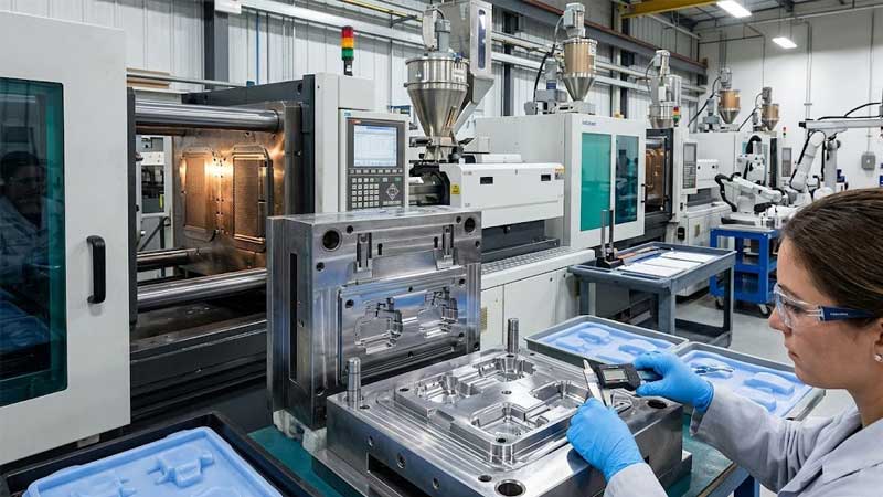
- DFM reviews catch undercut issues before mold fabrication. Early observation of ejection behavior allows tweaks before committing.
Small adjustments in draft, parting line, or bump-off location have disproportionate impact on part quality. Engineers often watch a part eject and tweak angles by 1–2° to optimize results. These subtle changes save hours of troubleshooting later.
Conclusion
Undercuts should only exist when function demands. Careful material choice, parting line planning, bump-off design, and side-action integration ensure high-quality, reliable production. Early collaboration between design and production teams avoids surprises, reduces scrap, and extends mold life.
Understanding how silicone behaves under pressure, how molds interact with features, and how minor adjustments affect production is key. Good design decisions upfront prevent weeks of costly troubleshooting. Reliable results come from observing, testing, and adjusting in real production conditions, not from arbitrary design rules.