Flash-free LSR parts are essential for medical, aerospace, and high-reliability sealing applications, yet achieving them consistently remains difficult. This article focuses on the two main factors that determine success—extremely tight mold tolerances and carefully timed vacuum logic—while touching on supporting elements like geometry, cold runners, and daily process control. The aim is to share practical approaches that have proven effective in real production.
Secondary Trimming – The Hidden Cost Driver
Hand deburring and 100% inspection under magnification often become the largest variable expense in U.S. silicone molding. On smaller medical seals, micro-gaskets, or sensor components, trimming labor plus related overhead can reach 40–60% of the final landed part cost. In one respiratory valve seal program we handled, the initial mold required full-shift trimming on every run; after targeted revisions the operation was eliminated and per-part cost dropped noticeably within two months.
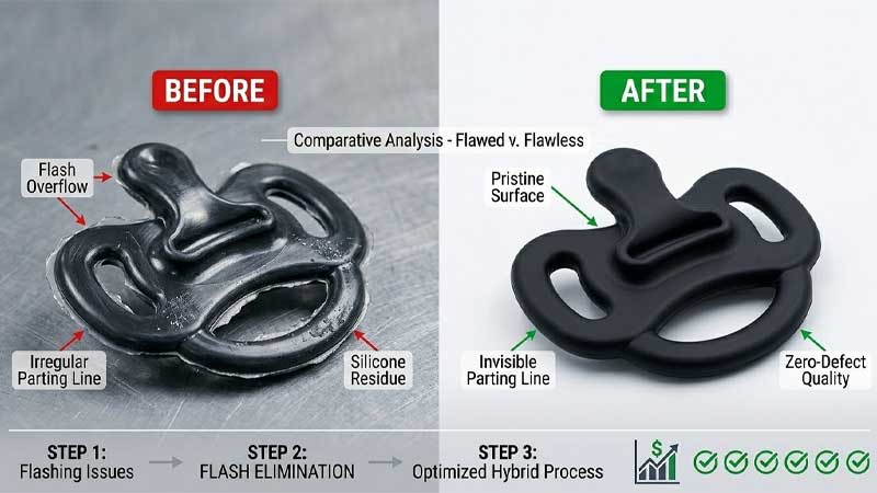
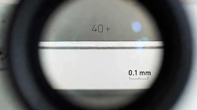
Regulated industries leave little room for rework. A detached flash fragment in an implant can lead to serious biocompatibility or mechanical issues. In sealing applications, even a 0.01 mm overflow lip can create leak paths or wear surfaces that fail qualification. Zero-flash means the parting line shows no material escape under 30–40× magnification—clean, smooth, and consistent.
LSR Flow Behavior and the Narrow Control Window
During injection, LSR viscosity drops below 500 cps, allowing it to penetrate gaps as small as 0.005 mm almost immediately. Unlike TPU or TPE, which shear-thicken rapidly and provide some forgiveness at the parting line, LSR remains fluid until platinum-catalyzed cross-linking begins late in the cycle.
Injection pressures of 80–150 bar (higher in micro-features) ensure complete fill, but they also cause slight mold-plate deflection—known as mold breathing. This microscopic opening occurs precisely when the material is still mobile. Molds that measure under 3 μm shut-off clearance at room temperature often show flash at 170–200 °C operating temperature unless thermal expansion differences between core and cavity are deliberately compensated.
Pillar I – Maintaining 5-Micron Shut-Off Tolerance
Steel choice provides the foundation. ESR-remelted S136 or premium H13, processed with multiple tempering cycles, delivers the dimensional stability needed for long runs.
Thermal expansion is a constant factor. Tool steel grows approximately 11–13 μm per meter per 100 °C rise. For a 300 mm mold base, the shift from ambient to operating temperature produces 0.05–0.07 mm total growth. Even small variations in heating uniformity or steel properties between core and cavity can open one side of the shut-off while closing the other.
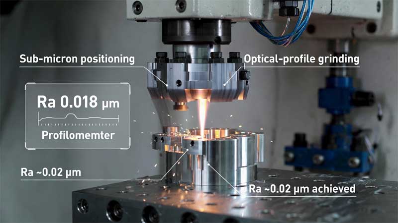
Design-stage thermal FEA helps predict movement, but the real calibration comes from in-press temperature mapping followed by fine geometry adjustments—typically 0.002–0.004 mm offsets on parting surfaces. Machining uses 5-axis nano-precision milling for roughing, then mirror-finish wire EDM or optical-profile grinding on shut-off bands to achieve Ra <0.02 μm. Rougher surfaces create escape paths that LSR exploits quickly.
Geometry Adjustments That Eliminated Flash
A client project involved an over-molded silicone bellows with sharp internal corners that concentrated pressure and caused flash at every transition. After a single mold revision, the changes were:
| Aspect | Original Design | Revised Design | Result |
| Corner Radii | 0.2 mm sharp transitions | 0.6–0.8 mm minimum radii | Peak pressure reduced 22–28% |
| Wall Thickness Transitions | Abrupt steps (0.4 to 1.2 mm) | 15° gradual taper over 2.5 mm | No jetting, smoother flow front |
| Gate Placement | Single edge gate at thick section | Two balanced fan gates | Even fill, 15% faster packing |
| Flash Occurrence | 62% of parts required trimming | Essentially zero | Trimming operation eliminated |
| Cycle Time | 52 seconds | 41 seconds | 21% throughput improvement |
These modest geometry changes delivered clean parts and faster cycles.
Pillar II – Vacuum Logic and Timing
Vent depth presents a classic trade-off. Conventional 10–20 μm vents allow flash; tighter 2–4 μm depths risk trapped air, burns, or short shots unless vacuum is applied effectively.
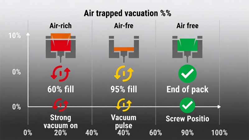
Pre-vacuum starts as soon as clamp force reaches 70–80%, clearing most cavity air before material entry. Staged vacuum, triggered by screw position or cavity pressure, provides finer control: a strong pull around 60% fill, followed by a brief high-vacuum pulse near 95% fill to extract final pockets without pulling silicone into vents.
Perimeter vacuum seal rings—a narrow groove outside the cavity connected to vacuum channels—have proven reliable. They maintain metal-to-metal shut-off while offering a controlled exhaust path. In one multi-cavity medical housing tool, this feature reduced flash-related rejects from 18% to under 1% and maintained that level past 100,000 shots.
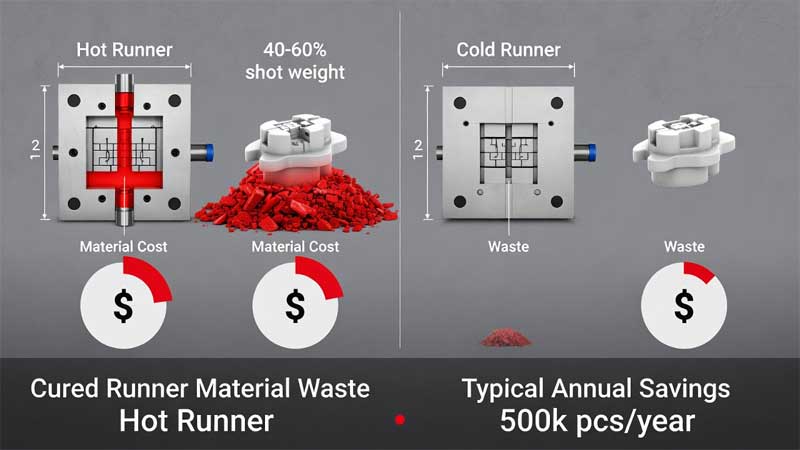
Cold-Runner Systems – Economic Reality
Cold runners eliminate cured runner waste (typically 30–60% of shot weight) and reduce cycle time by 15–30%. For a representative 500,000-piece/year micro-seal program:
- Conventional mold: $85k tooling, ~12% material waste, 48 s cycle, trimming required
- Cold-runner mold: $102k tooling (+$17k), <2% waste, 36 s cycle, no trimming
At typical platinum-cure LSR prices, material savings alone recovered the added cost in about 4.5 months. Including labor savings and improved press utilization, payback often falls to 3–4 months.
Total landed cost is the better metric than mold price. A well-engineered zero-flash tool may cost 25–40% more initially, but it removes scrap, rework, and validation delays.
Process Discipline to Prevent Gradual Drift
Cavity-pressure-triggered V/P switchover at 95–98% fill prevents over-packing while ensuring complete detail reproduction. Mold temperature uniformity of ±2 °C across all surfaces avoids localized expansion that causes one-sided flash; thermal imaging during commissioning confirms even heating.
Shut-off surfaces require cleaning every 40–60k shots. Silicone residue and release agents build thin films that can exceed design clearance. A routine of ultrasonic cleaning, solvent wipe, and microscopic inspection stops the slow return of flash.
Conclusion
Zero-flash LSR molding depends on tight integration of mold tolerances, vacuum strategy, geometry optimization, and consistent process control. When these elements align, secondary operations disappear, quality risks drop, and overall economics improve significantly.