In this article, we will explore the differences between STL and STP file types and explain how choosing the right format can impact silicone part development. You will see how each file type affects mold design, surface precision, and production workflow, helping you make informed decisions for efficient manufacturing.
Why File Format Matters in Silicone Manufacturing
When a silicone project begins, manufacturers usually ask for one thing very early in the process. They need the 3D design file. Most of the time the file arrives as either STL or STP.
At first there seems to be little difference. Both files open normally. The product shape looks correct. From a visual point of view, everything appears ready for the next step.
The situation changes once engineering work starts.
The type of file used can influence several parts of the development process:
- quotation accuracy
- mold design efficiency
- dimensional control
- engineering revisions
- communication between designers and factories
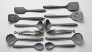
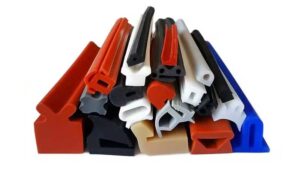
In silicone manufacturing this detail becomes important quite quickly. Products such as keypads, seals, baby accessories, or wearable components rely on precise geometry. Some file formats are perfectly fine for visualization or prototype printing. Others are far more practical when molds must be designed and built.
Knowing how STL and STP behave during real production work can prevent delays that often appear later in a project.
What Is an STL File?
A Format Built Around Mesh Geometry
STL stands for Stereolithography. The format was introduced during the early development of 3D printing technology.
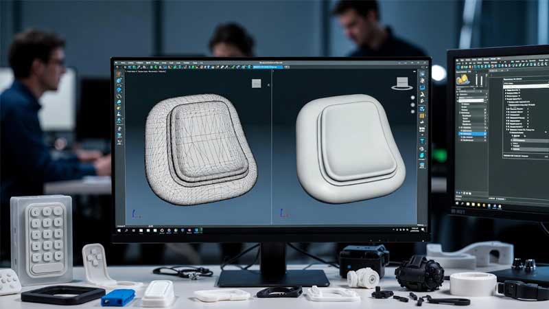
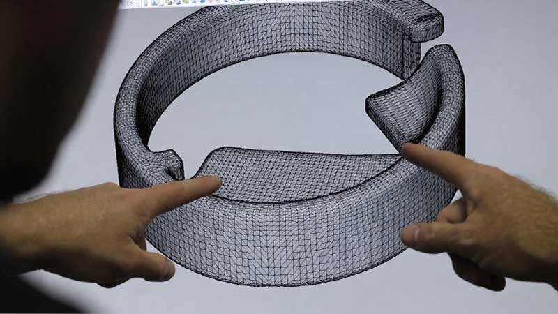
Instead of storing true curved surfaces, an STL model describes the shape using many small triangles. These triangles connect together and form a mesh that represents the outside of the object.
Each triangle is flat. Curved areas are created by combining a large number of these small surfaces. When the triangle count increases, the curve appears smoother to the eye.
| Feature | STL Characteristics |
| Geometry type | Triangular mesh |
| Surface accuracy | Approximation |
| Editable CAD features | No |
| Typical use | 3D printing |
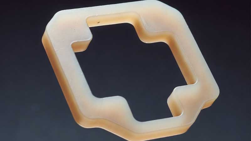
As an example, a silicone gasket with a circular profile may appear perfectly round when viewed in STL. In reality the circle consists of many tiny straight edges. For visualization this difference is rarely noticeable. For engineering work it can become more relevant.
Where STL Files Are Commonly Used
STL works well in situations where visual shape is more important than exact geometry.
Typical applications include:
- 3D printed prototypes
- concept models
- early design evaluation
- product visualization
During the early stage of product development this approach is very practical. Designers often print a quick sample to check size or ergonomics.
For silicone products this helps evaluate things such as:
- how a product fits in the hand
- button spacing
- interaction between parts
- overall proportions
At this stage STL files are easy to share and quick to print. The limitations usually appear later when tooling begins.
What Is an STP File?
STP, also known as STEP, follows the ISO 10303 standard used for exchanging CAD models.
Unlike STL, an STP file stores actual geometric surfaces. The curves and shapes are defined mathematically inside the model.
Because of this structure, CAD systems can recognize true geometric features such as:
- cylinders
- arcs and fillets
- complex surfaces
- solid bodies
These features remain editable in most engineering software.
| Feature | STP Characteristics |
| Geometry type | Solid and surface model |
| Surface accuracy | Exact mathematical geometry |
| Editable | Yes |
| Typical use | Engineering and mold design |
Most professional CAD systems support STP files. Examples include:
- SolidWorks
- Siemens NX
- CATIA
- Creo
This wide compatibility is one reason why STP has become a common format when design teams work with manufacturers.
STL vs STP: The Key Differences for Silicone Projects
When both file types are opened in a viewer, the product may look identical. The difference becomes clear once engineers begin preparing the mold design.
The comparison below highlights the points that matter most in silicone manufacturing.
| Feature | STL | STP |
| Geometry type | Mesh | Solid |
| Precision | Approximate | Exact |
| Editable | No | Yes |
| Surface definition | Triangles | Mathematical surfaces |
| Mold design suitability | Poor | Excellent |
| Typical file use | 3D printing | Engineering design |
For most silicone production projects, STP allows the engineering work to move forward more efficiently.
Why STL Files Often Create Problems in Silicone Mold Design
STL files are common because they are easy to export and easy to view. Many projects begin this way. The issues usually appear once engineers start working on the mold structure.
These problems are easier to see in parts that contain functional surfaces or tighter tolerances.
Surface Precision and Sealing Performance
Many silicone products depend on compression sealing.
Examples include:
- waterproof gaskets
- medical seals
- food container rings
- valve membranes
In these products the sealing surface must remain consistent.
Because STL models are made from triangles, curved surfaces contain many small segments. The deviation is usually small, but sealing structures can be sensitive to this type of geometry.
A silicone gasket typically works within a compression range around 20 to 30 percent. When the sealing surface is not perfectly smooth, pressure distribution may become uneven.
Possible results include:
- small leakage paths
- uneven compression
- unstable sealing performance
STP models avoid this issue because the surfaces remain mathematically smooth.
Difficulty When Adjusting Draft Angles
Draft angles are required for molded silicone parts. They allow the product to release from the mold more easily.
Typical guidelines are shown below.
| Surface type | Recommended draft |
| smooth surface | 1° to 2° |
| textured surface | 2° to 3° |
| deep cavities | 3° or more |
When engineers work with STP models, adding draft is usually straightforward. CAD tools can modify the surfaces without damaging the geometry.
STL models behave differently. Since the structure is based on triangular facets, surface editing becomes difficult. Engineers often rebuild certain areas of the model before draft can be applied.
This step adds extra work before mold design can continue.
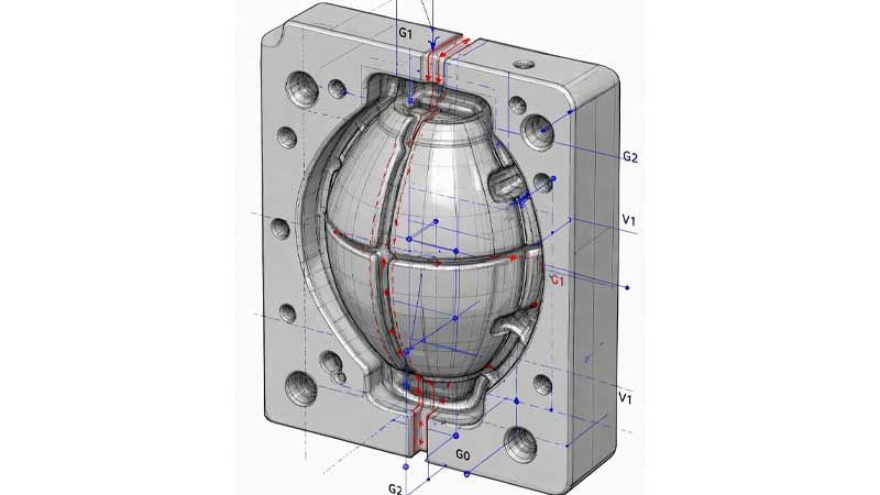
Parting Line Design Becomes Complicated
A well planned parting line is important in silicone mold design.
It influences factors such as:
- flash control
- product appearance
- mold durability
With a solid STP model, engineers can study the geometry and select a proper mold opening direction.
In an STL mesh, surface boundaries are less clear. The model still looks correct visually, but CAD systems struggle to identify precise edges. Engineers may need to rebuild parts of the geometry before defining the parting line.
Situations Where STL Files Are Still Useful
Despite these limitations, STL still plays a useful role during early product development.
Many silicone projects begin with STL prototypes.
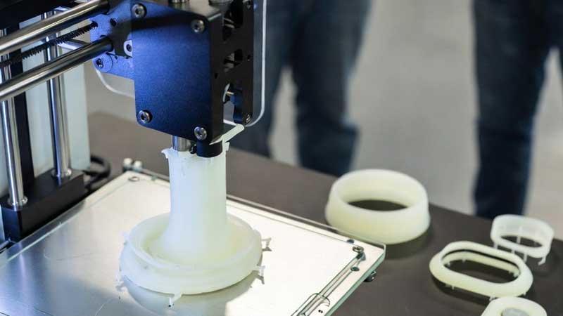
Rapid Prototype Evaluation
STL works well with SLA and SLS printing systems, which operate using mesh data.
Design teams often print early samples to evaluate:
- ergonomics
- button layout
- product size
- interaction with other components
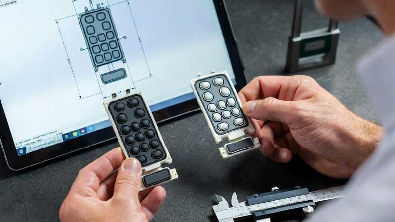
For example, when developing a silicone keypad, several layouts may be printed to check button spacing and finger reach.
Once the design feels correct, the geometry can be finalized and exported again as an STP model for tooling.
Quick Communication During Early Design
Another advantage of STL is convenience. The files are relatively small and many viewers can open them.
This makes STL useful for sharing early concepts across different teams. Industrial designers, engineers, and marketing staff can review the model without specialized CAD tools.
When detailed engineering begins, STP becomes the more suitable format.
Why Silicone Manufacturers Prefer STP Files
Manufacturers that specialize in silicone molding usually request STP files when a project begins.
The reason is simple. STP integrates better with the tooling workflow.
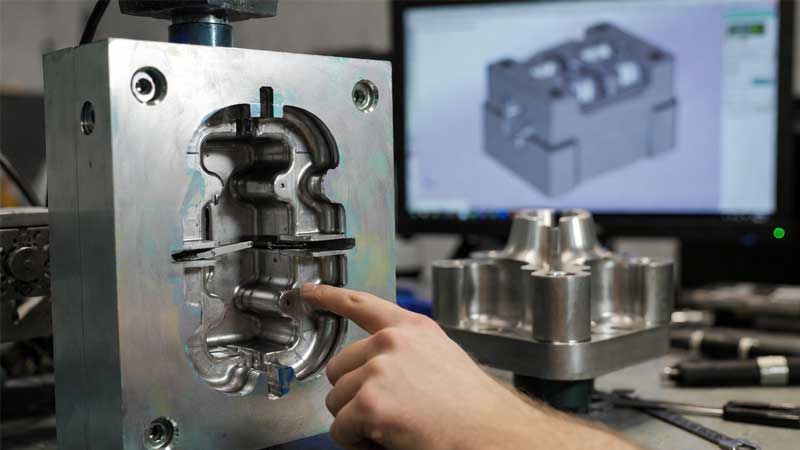
Faster Mold Engineering
An STP model allows engineers to begin mold design immediately.
Typical tasks include:
- defining parting surfaces
- designing gates and runners
- creating venting channels
- adjusting draft angles
These operations rely on accurate surface geometry. STP files provide the required data from the start.
If only an STL model is available, engineers often spend additional time rebuilding geometry before mold work can begin.
More Reliable Dimensional Control
Silicone components frequently contain functional structures such as:
- snap connections
- sealing ribs
- button domes
These structures depend on accurate dimensions.
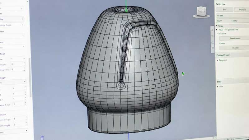
Consider a silicone keypad dome. The dome shape determines the travel distance and tactile force of the button. Small geometry changes can alter the feel of the switch.
STP files preserve curves and dimensions more reliably.
Easier Collaboration Across Engineering Teams
Product development often involves several groups:
- product designers
- silicone manufacturers
- mold makers
Each group may use different CAD platforms. STP works as a neutral exchange format that most systems can read.
This helps teams share models without losing important geometry data.
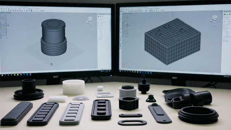
Recommended File Types for Silicone Product Development
When sending files to a silicone manufacturer, several formats are commonly accepted.
| File Type | Usefulness for Production |
| STP / STEP | Best option |
| IGES | Good alternative |
| STL | Acceptable for prototype review |
| 2D drawings | Useful for tolerance control |
In many cases the most effective combination is:
an STP model together with a 2D engineering drawing
The 3D model defines the shape. The drawing specifies details such as:
- critical dimensions
- tolerance limits
- material hardness
- surface finish
This approach helps avoid confusion during tooling.
A Common Situation: Converting STL to STP
Occasionally only an STL model is available.
It is possible to convert STL into STP, although the process requires several steps.
Typical workflow:
- repair mesh errors
- reconstruct surfaces
- generate solid geometry
For simple parts the conversion may work reasonably well. For complex products the reconstruction stage can require significant manual work.
Even after rebuilding the model, small differences may remain. Because of this, exporting the STP file directly from the original CAD system is usually the safer option.
Practical Tips Before Sending Files to a Silicone Manufacturer
A few simple checks before sending the design files can help avoid delays.
The following points are worth confirming.
| Check Item | Why It Matters |
| Provide STP model | Allows direct mold design |
| Include draft angles | Prevents molding issues |
| Mark critical dimensions | Ensures functional accuracy |
| Specify material hardness | Influences shrinkage and flexibility |
| Clarify tolerance requirements | Important for sealing and assembly |
These preparations reduce repeated communication and help the project move forward more smoothly.
Conclusion
Both STL and STP have their place in product development. STL works well for early concept models and quick prototype printing. STP is far more practical for detailed engineering and mold production.
For silicone components that depend on accurate geometry, STP provides clear advantages. Mold engineers can work more efficiently, dimensional control becomes easier, and collaboration between teams improves.
Selecting the appropriate fi le format early in the project often saves time during tooling and helps ensure the final silicone product performs as inten ded.
With years of experience and advanced silicone molding technology, we are ready to turn your designs into high-quality, functional silicone products. Contact us today to discuss your custom project and see how our expertise can bring your ideas to life.