Designing a silicone product without a precise drawing is like building a house without a blueprint. It leads to miscommunication, wasted molds, and costly delays.
Accurate silicone product drawings ensure correct dimensions, material behavior, and manufacturability—critical for prototyping and large-scale production.
A well-prepared drawing helps engineers, mold makers, and suppliers stay aligned from day one. It eliminates guesswork and speeds up approvals and production.
Why Are Technical Drawings Crucial for Silicone Products?
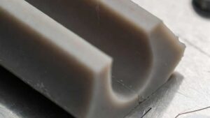
Silicone behaves differently than metals or plastics. It stretches, compresses, and rebounds in unique ways.
Technical drawings guide every step of silicone product development—from material selection to mold design—ensuring dimensional accuracy and functional performance.
When I started working with silicone, I learned the hard way that generic drawings weren’t enough. A missing tolerance or radius caused molds to fail—and cost us weeks.
What Drawings Communicate
| Element | Purpose |
|---|---|
| Dimensions | Define size, thickness, inner/outer diameters |
| Tolerances | Allowable deviations for flexible material |
| Material Specs | Type, shore hardness, curing method |
| Surface Finish | Important for grip, sealing, or appearance |
| Assembly Notes | Show fit with other components |
| Cross-Sections | Reveal internal structure or cavities |
These details ensure the supplier knows exactly what you want—and that what you get matches your design.
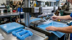
What Format Should You Use for Silicone Product Drawings?
The right format keeps your drawing compatible with manufacturing software and inspection tools.
For silicone products, use 2D CAD drawings in PDF for reviews and DXF or DWG for mold design and CAM programming.

In my experience, starting with a clean 2D PDF avoids confusion. Then, if needed, I share the original CAD files for the toolmaker. This step-by-step approach keeps everything traceable and flexible.
Recommended File Types
| File Type | Use Case |
|---|---|
| Universal sharing and review | |
| DXF / DWG | Tooling and CNC programming |
| STEP / IGES | 3D modeling and simulations |
| STL | 3D printing for prototyping |
Stick to clean, well-layered files with clear annotations. Avoid exporting messy or dimensionless views.
What Dimensions and Tolerances Should Be Included?
Silicone compresses and stretches—so exact dimensions aren’t always achievable or necessary.
Always include inner and outer diameters, wall thickness, radii, and critical functional zones with tolerances suited for silicone.

I typically use ±0.3 mm for general tolerances and ±0.1 mm for critical sealing features. But every project is different—collaborate with your manufacturer early.
Common Dimensioning Tips
- Wall Thickness: Keep uniform to prevent flow issues.
- Radii: Add generous curves to avoid tearing.
- Parting Line: Mark for visual and sealing consistency.
- Undercuts: Flag clearly—they require special tooling.
- Draft Angles: Usually not required, but helpful for demolding.
| Feature | Suggested Tolerance |
|---|---|
| Outer Diameter | ±0.3 mm |
| Inner Diameter | ±0.2 mm |
| Wall Thickness | ±0.2 mm |
| Length / Height | ±0.5 mm |
| Seal Surface | ±0.1 mm |
These are starting points. Final tolerances should be verified with your silicone supplier based on tooling and material behavior.
How Do You Account for Material Shrinkage?
Shrinkage happens as silicone cools and cures. If ignored, it throws off your final dimensions.
Always factor in shrinkage—typically 1% to 3% depending on the silicone compound and mold design.

For one of our baby bottle nipple designs, the part came out 1.5 mm too short. Turned out we didn’t include shrinkage in the mold. After adjusting the CAD drawing, everything fit perfectly.
How to Handle Shrinkage
- Ask your supplier for specific shrinkage rates of their compound.
- Add shrinkage factor into mold design—not final product drawing.
- Use 3D simulation tools if tolerances are critical.
Never assume shrinkage is uniform. Wall thickness, mold temperature, and curing time can affect it unevenly.
Should You Include Notes and Callouts?
Yes—notes guide manufacturing, avoid confusion, and prevent rework.
Use callouts to highlight material grade, surface texture, hardness, and any special instructions like vent holes or overmolding.

I always include notes like “Use FDA-approved platinum silicone, Shore A 60” or “Gate location must be on non-visible surface.” These small details save hours of back-and-forth later.
Must-Have Callouts
- Material type: e.g. “Platinum-cured, FDA-grade silicone”
- Hardness: e.g. “Shore A 50 ±5”
- Curing method: e.g. “Compression mold, post-cured 4 hours at 200°C”
- Special features: “Include ventilation holes Ø1 mm”
- Color: e.g. “Pantone 2707C, matte finish”
Clear notes reduce interpretation errors—and make life easier for your tooling and quality control teams.
What Tools Can Help Create Better Drawings?
Creating accurate silicone drawings doesn’t require a huge budget—just the right tools and process.
Use CAD software like SolidWorks, AutoCAD, or Fusion 360 to design and export clean, detailed technical drawings with silicone-specific tolerances.
I use Fusion 360 for quick iterations and SolidWorks for final drawings. I pair this with feedback from my silicone supplier to refine dimensions.
Recommended Tools
| Tool | Purpose |
|---|---|
| Fusion 360 | Easy modeling + cloud collaboration |
| SolidWorks | Industry-standard precision drawings |
| AutoCAD | Great for 2D profile control |
| Rhino | Ideal for complex organic shapes |
| Adobe Illustrator | Clean up vector drawings for presentation |
Even if you’re not an engineer, working with a CAD designer who understands silicone manufacturing can dramatically improve the outcome.
Conclusion
Accurate silicone product drawings combine clear dimensions, material specs, and realistic tolerances—ensuring successful manufacturing from concept to mass production.