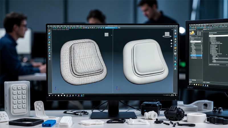
Silicone mold design can be tricky. Small design flaws can lead to costly defects and wasted time.
Effective silicone mold design depends on precise control of venting, parting lines, tolerances, and shrinkage to ensure product quality and manufacturability.
Every decision in mold design affects how the final product performs. By understanding each factor early in the process, we can avoid common production pitfalls and achieve stable, high-quality molding results.
Flow and Venting?
Good venting prevents air traps and burn marks. Poor venting causes bubbles, incomplete fills, or surface defects.
Venting allows trapped air to escape during injection. Balanced venting ensures complete filling and a smooth product surface.
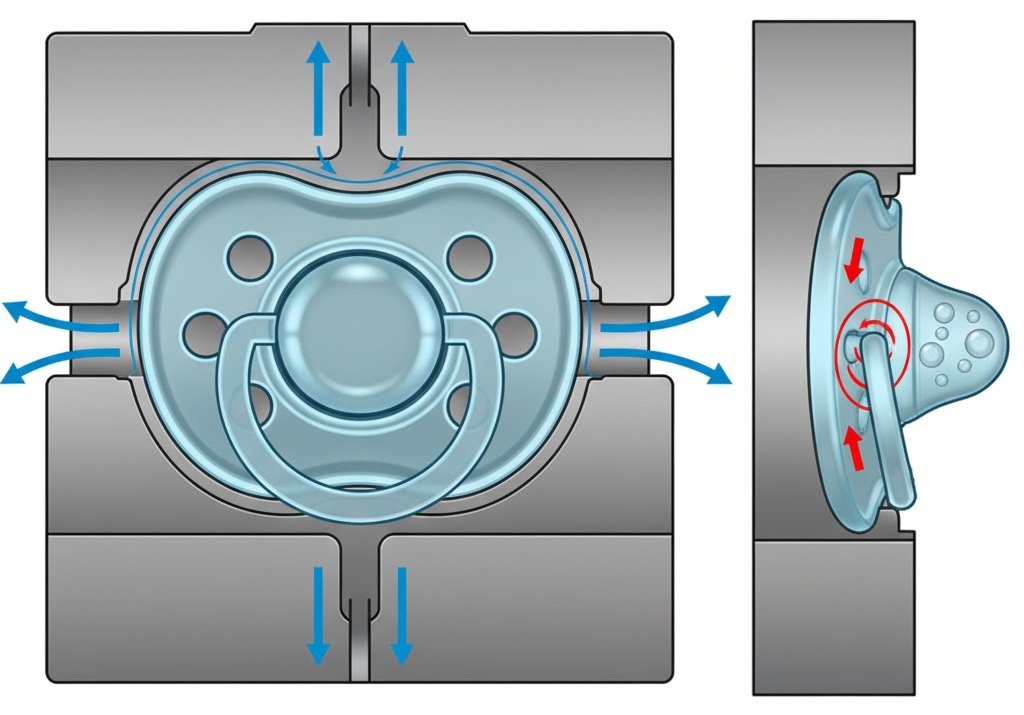
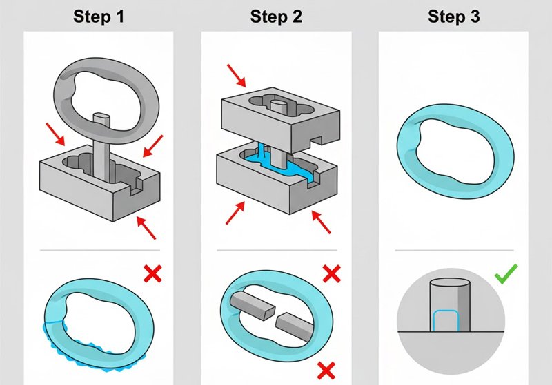
Air traps are a common challenge in silicone molding because liquid silicone rubber (LSR) has high viscosity and tends to trap air in narrow areas. When I worked on a pacifier mold last year, improper venting caused several rejects with bubbles near the nipple area. That taught me how critical venting design is.
Key Venting Design Guidelines
| Parameter | Typical Value | Notes |
|---|---|---|
| Vent depth | 0.005–0.02 mm | Too shallow traps air; too deep causes flash |
| Vent width | 3–6 mm | Enough for air flow without silicone leakage |
| Vent location | Far from gate | Avoid silicone backflow |
Vents should be placed at the last filling point and evenly around the cavity. In complex geometries, micro-vents or vacuum assistance may be needed. Vacuum systems help ensure bubble-free products for medical and baby care items, where clarity and smooth surfaces are essential.
Parting Line Strategy and Flash Control?
Flash defects often indicate parting line issues. Poor line placement increases trimming costs and reduces yield.
A well-planned parting line minimizes flash and improves product aesthetics while ensuring demolding feasibility.
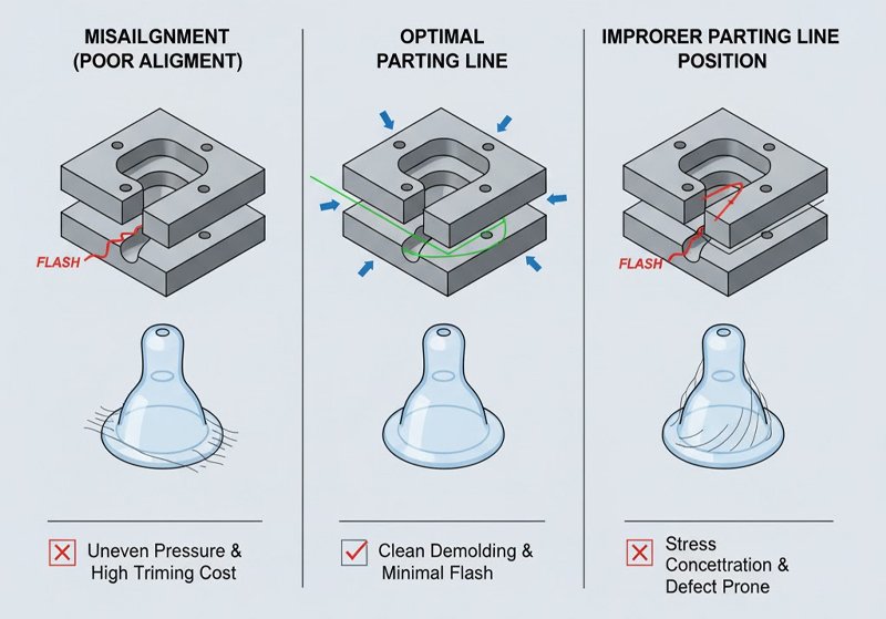
I still remember a project where a bottle nipple mold kept producing thin flash along the sealing edge. After reviewing the tool, I realized the parting line was placed in a high-pressure zone. Relocating it reduced flash dramatically.
Strategies for Flash Control
- Place the parting line along natural geometry transitions. Avoid sharp edges that concentrate stress.
- Maintain precise alignment. Misalignment between mold halves creates uneven pressure, leading to flash.
- Control clamping force. Insufficient pressure allows silicone to seep through the parting line.
- Polish and maintain sealing surfaces. Wear or dirt buildup can cause leaks.
Common Root Causes of Difficult-to-Control Flash
| Root Cause | Typical Symptoms | Recommended Solution |
|---|---|---|
| Poor mold alignment | Asymmetric flash | Regrind and realign mold halves |
| Excessive vent depth | Long, thin flash | Reduce vent depth to 0.005 mm |
| Improper parting line position | Flash around visual areas | Reposition line or modify design |
Flash control is both a design and maintenance issue. Routine inspection of sealing surfaces helps sustain quality over the mold’s lifetime.
Overmold Tolerances and Positioning?
Precise alignment is essential in overmolding. Misalignment can lead to uneven bonding or functional failure.
Overmold tolerance control ensures the secondary silicone layer bonds properly to the base component.
When designing baby bottle handles, we often deal with two-step molding — first the rigid insert, then the silicone overmold. If the insert shifts even slightly, the soft layer becomes uneven or peels off easily.
Critical Factors in Overmold Design
| Parameter | Target Range | Impact |
|---|---|---|
| Insert positioning accuracy | ±0.02 mm | Misalignment causes uneven bonding |
| Overmold thickness | ≥1.0 mm | Ensures uniform flow and bonding |
| Interface surface roughness | Ra 0.4–0.8 | Improves adhesion |
Designers should include mechanical locks or undercuts where possible to improve bonding. Avoid air traps at the interface by adding venting near the bonding zone. For optical-grade silicone or baby products, ensure surfaces are free of contaminants that may inhibit curing.
Cold Runner vs. Hot Runner Selection (LSR)?
Runner design influences cost, waste, and temperature stability. Choosing the right system affects efficiency.
Cold runners reduce waste and maintain material stability, while hot runners are better for high-volume, consistent production.
During a project for a baby spoon mold, I compared both systems. The cold runner reduced waste but increased cycle time slightly. The hot runner gave faster cycles but required stricter temperature control.
Comparison Table
| Feature | Cold Runner | Hot Runner |
|---|---|---|
| Material waste | Minimal | Some |
| Cost | Lower initial cost | Higher tooling cost |
| Temperature control | Easier | Critical |
| Cycle time | Longer | Shorter |
| Best for | Small or medium runs | High-volume production |
FAQ: Is Cold Runner Recommended for Small Batch Production?
Yes. For small-batch or prototyping projects, cold runners are more cost-effective. They simplify maintenance and reduce material waste, which is ideal when testing product design changes.
Demolding Mechanisms and Surface Textures?
Demolding defines product finish and cycle time. Poor demolding design leads to tearing or deformation.
Proper demolding and surface texture selection ensure smooth release and maintain product quality.
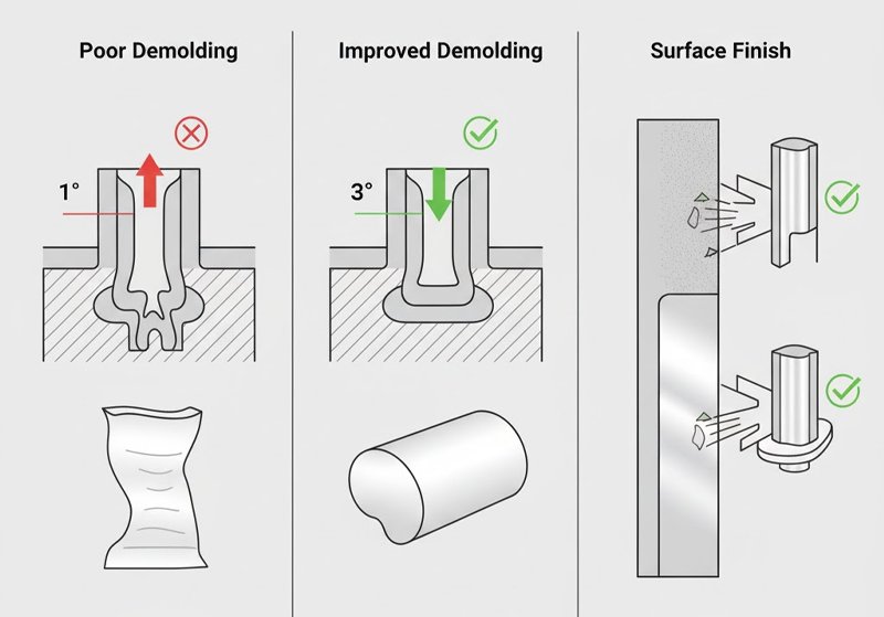
Silicone tends to stick due to its elasticity. In one project, we struggled with parts tearing during ejection. Adjusting the draft angle from 1° to 3° and polishing the core surface solved the issue.
Tips for Better Demolding
- Increase draft angles to 2–5° for deep cavities.
- Use matte or fine EDM texture for consistent release.
- Apply air-eject or mechanical stripper systems to assist demolding for complex shapes.
- Avoid undercuts unless necessary; use collapsible cores if required.
Surface finish affects not just appearance but also release behavior. For baby or medical items, mirror polishing is often used to reduce particle accumulation and ensure hygiene.
Shrinkage Rate and Deformation Prediction?
Shrinkage is unavoidable in silicone molding. Ignoring it causes dimensional deviations and assembly issues.
Predicting shrinkage and compensating in the mold design phase ensures part accuracy and stable performance.
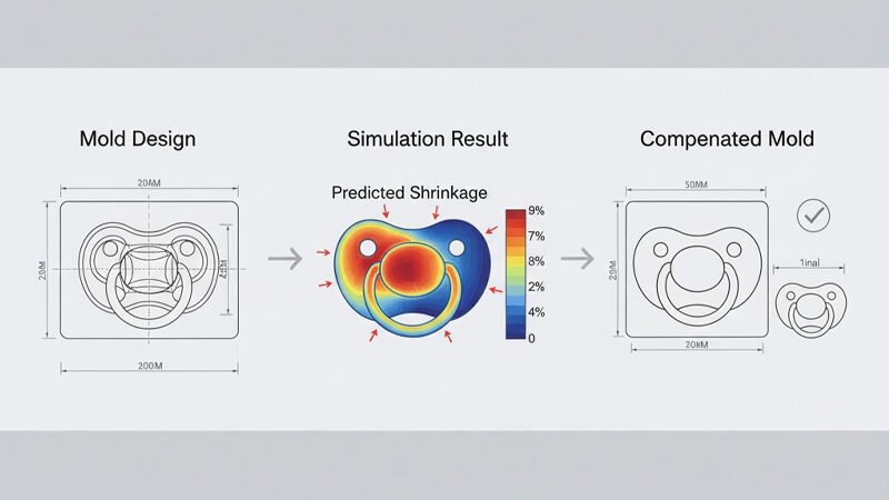
In my early projects, I underestimated LSR shrinkage and had to remake a mold due to undersized parts. Now, I always model shrinkage based on real process data before finalizing steel dimensions.
Typical LSR Shrinkage Data
| Material Type | Shrinkage Rate | Notes |
|---|---|---|
| General LSR | 2.0–3.5% | Depends on cure temperature and pressure |
| High-precision LSR | 1.5–2.0% | Optimized for optical or medical use |
Predictive tools like Moldflow or SIGMASOFT can simulate flow and shrinkage behavior. Inputting correct curing parameters improves prediction accuracy. Always validate simulation with test shots and measure actual shrinkage before mass production.
Conclusion
Silicone mold design requires precision in every detail. By mastering venting, parting lines, tolerances, runners, demolding, and shrinkage, we can achieve consistent, defect-free production.
Ready to optimize your silicone mold design?
Upload your product 3D files and key requirements to receive a custom DFM checklist from our engineering team at RuiYang Silicone.